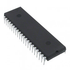
Specifications for a microcontroller:
• Switch-on reset (POR)
• PWRT (Power-up Timer) and
Timer for Oscillator Startup (OST)
• For dependable operation, Watchdog Timer (WDT) has an on-chip RC oscillator.
Programmable code defence
• Sleep mode, which saves power
• Variable oscillator choices
• Serial In-Circuit Programming using two pins
The STATUS register houses the bank select bits for data memory, the RESET state, and the ALU's arithmetic status.
The TMR0 pre-scaler/WDT post-scaler (single assignable register also known as the pre-scaler), the External INT Interrupt, TMR0, and the weak pull-ups on PORTB may all be configured using the different control bits found in the OPTION REG register, which is a reading and write register.
The TMR0 register overflow, RB Port change, and External RB0/INT pin interrupts are all enabled and flagged in the INTCON register, which is both readable and written.
Program memory may be addressed in a continuous 8K word block by PIC16F7X devices. Only 11 bits of address are provided by the CALL and GOTO instructions, allowing branching inside any 2K programme memory page. PCLATH4:3> provides the upper 2 bits of the address when performing a CALL or GOTO instruction. The user must make sure that the page choose bits are set when performing a CALL or GOTO instruction in order for the chosen programme memory page to be addressed. The full 13-bit PC is popped off the stack upon the execution of a return from a CALL instruction (or interrupt).
3rd Floor, 3c , Manek Chambers, above vasant bhuvan, LAMINGTON ROAD, GRANT ROAD,, Mumbai 400007